Automata Workshop
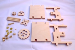
I have now designed and cut the basic mechanism. Next job, which could take some time, is to design and carve the figure and decide what movements are required.
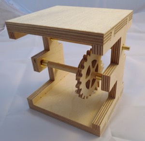
I have made a frame for the prototype that I can easily take apart for fitting the gears and cams.
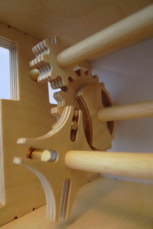
The axles have brass ferrules and I have recessed the frame to take brass bushes. A simple wooden axle can work well but the brass work introduces a greater level of accuracy. If using wooden axles there is always some fiddling to get the Geneva Wheel to engage properly.
The frame and drive cog are made from 12mm birch ply. The rest of the mechanism is made form 6mm birch ply.
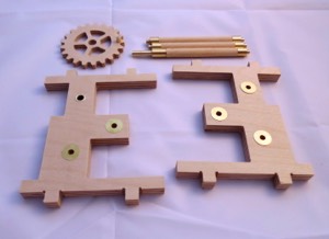
The parts with the brass work fitted. All is push fit but the pin in the Geneva Wheel in held in place with superglue.
The assembled frame and gears. This arrangement makes the basis of most of my automata designs.
There are 3 axles running at different speeds. The Geneva Wheel axle can be used to switch the cams off and on on the other axles.
There are 3 axles running at different speeds. The Geneva Wheel axle can be used to switch the cams off and on on the other axles.
It is important in the design stage to ensure that none of the gears etc hit the other axles.
Proof that wooden gears are effective. This video shows the mechanism being driven by a power drill at 1500 RPM.
Most people would turn an automaton handle at between 30 and 60 RPM. I think this mechanism is up to the job!
Most people would turn an automaton handle at between 30 and 60 RPM. I think this mechanism is up to the job!