Making Cute Cow
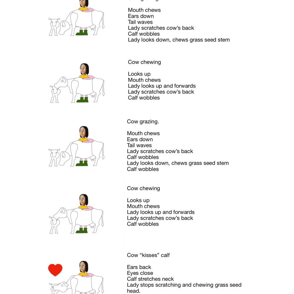
First comes the proposal. The actors in the scene and the scenario that they play out. In the original proposal I though that the calf would be standing but once I started mocking up the piece I realised that it will work better with the calf lying down.
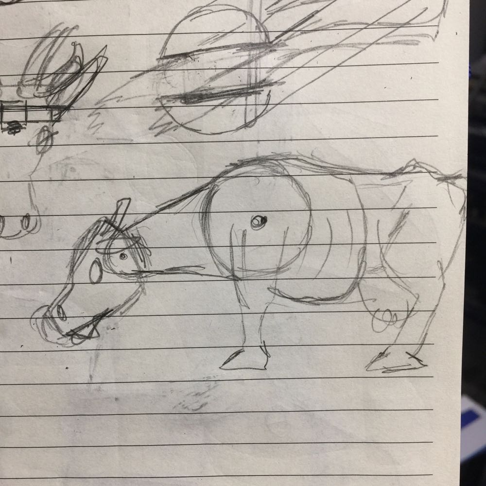
When starting a new project I spend time just mulling over the idea in my head and then I start making many rough sketches of form and also how the movement might work.
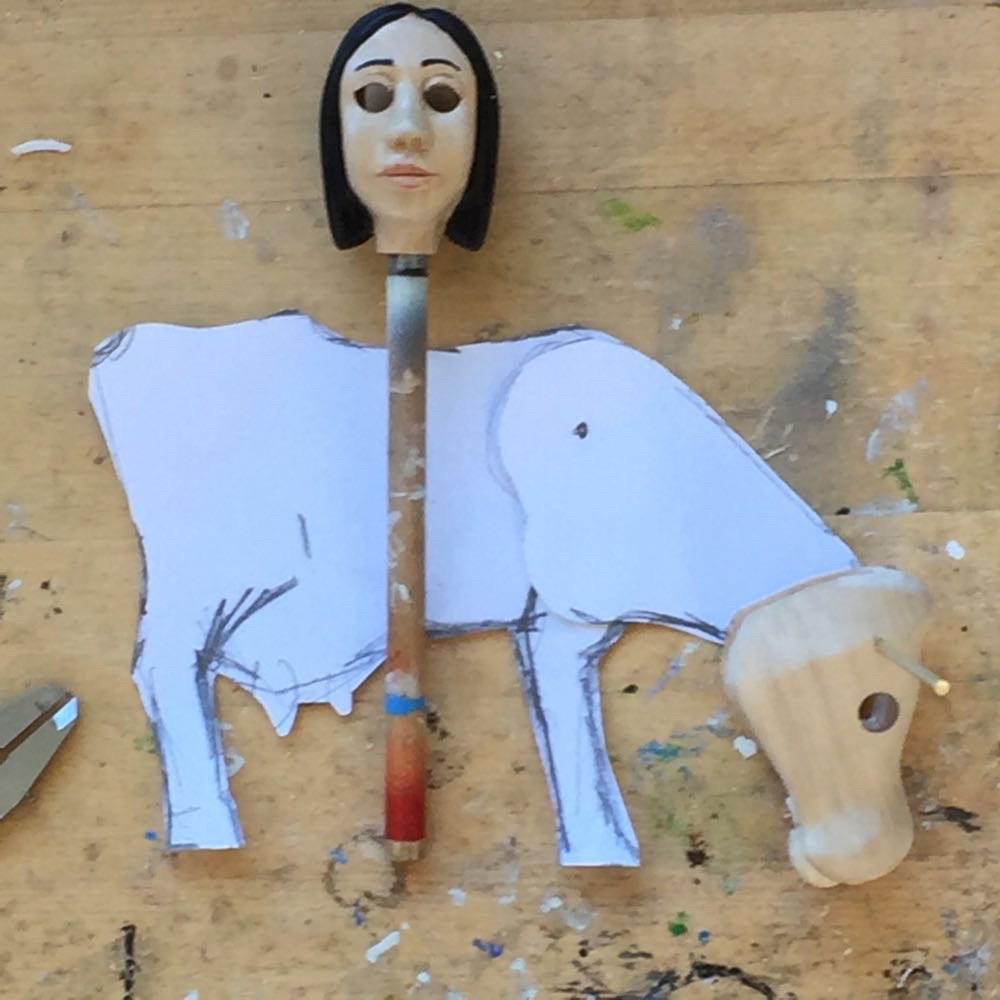
I then make rough paper cut-outs to get an idea of the best scale. The various movements can be check by making pin joints between the paper parts.
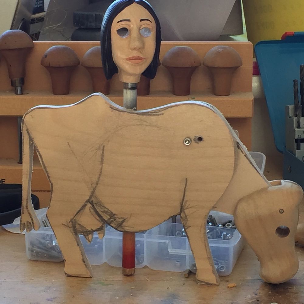
Once I happy about the rough design I cut out a ply template with my fretsaw. The parts can now be bolted together to get a better idea of how the automaton will work. The head is a first draft used in the proposal and has been revised for the finished piece.
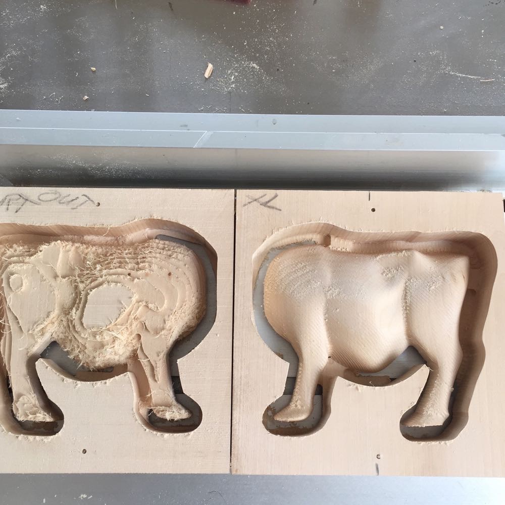
The ply cut-out is photographed and imported into Blender to act as a guide for creating the 3D file for the part. This is then cut with the router. The cutting can take several hours for each part.
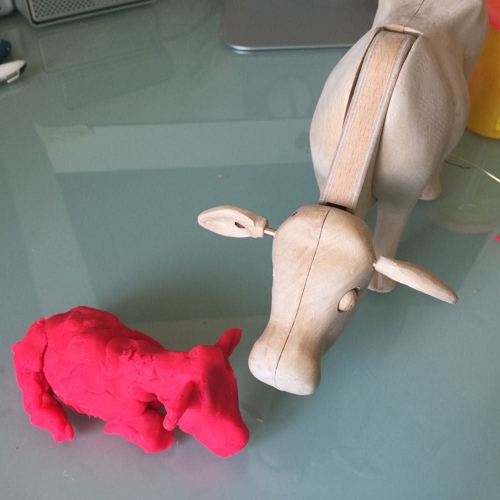
For more complicated shapes I will make a rough model with PlayDoh. I use this because it is soft and easy to work. I take photographs of the PlayDoh model for use as a guide in Blender. 3D modelling in Blender is time consuming and takes a lot of concentration but the effort is worth is as the results are then precise and repeatable.
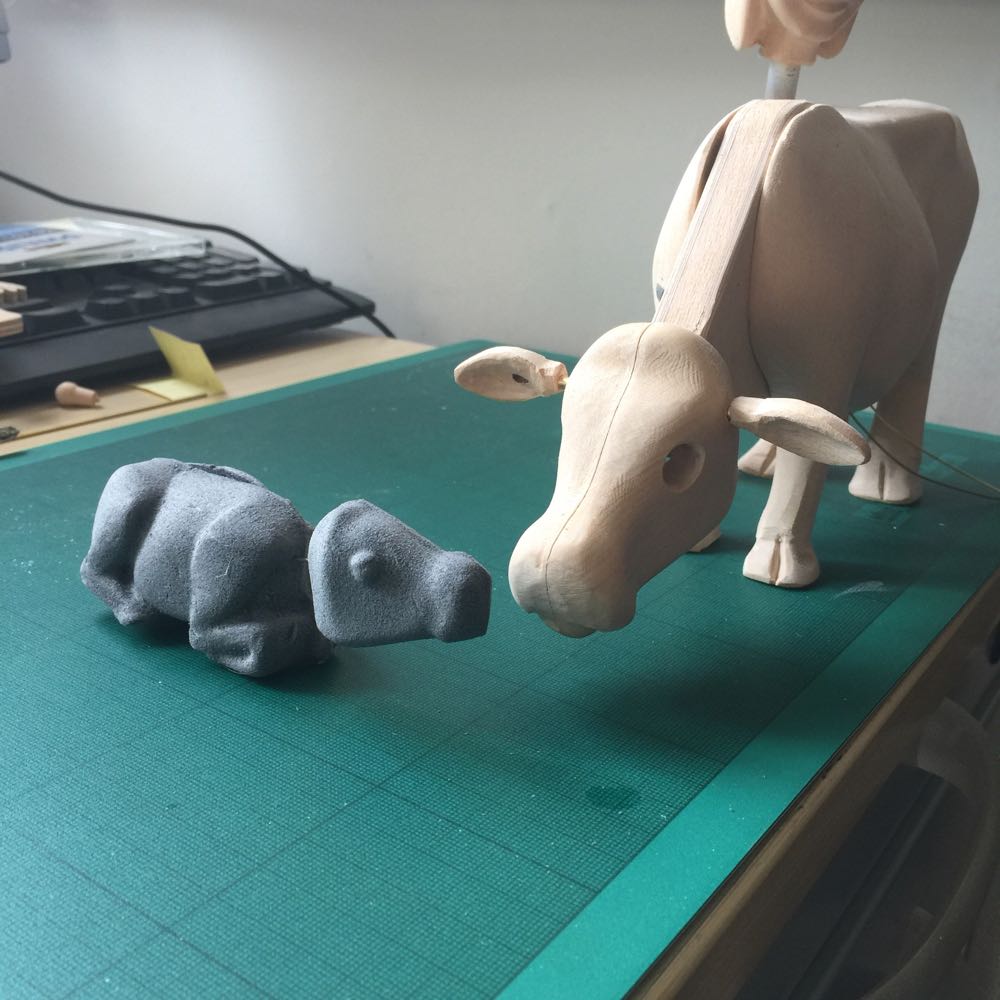
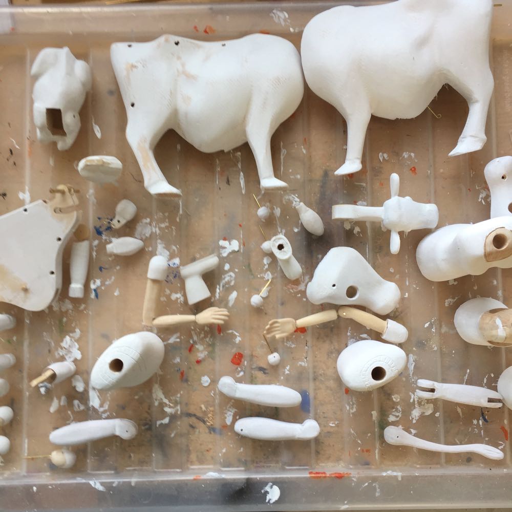
I have now started cutting the prototype model out of foam. This is quicker than wood and the parts are easy to attach with pins. It is difficult to judge scale on the computer screen and a size difference of only a couple of millimetres can make a big difference to the aesthetic of the piece.
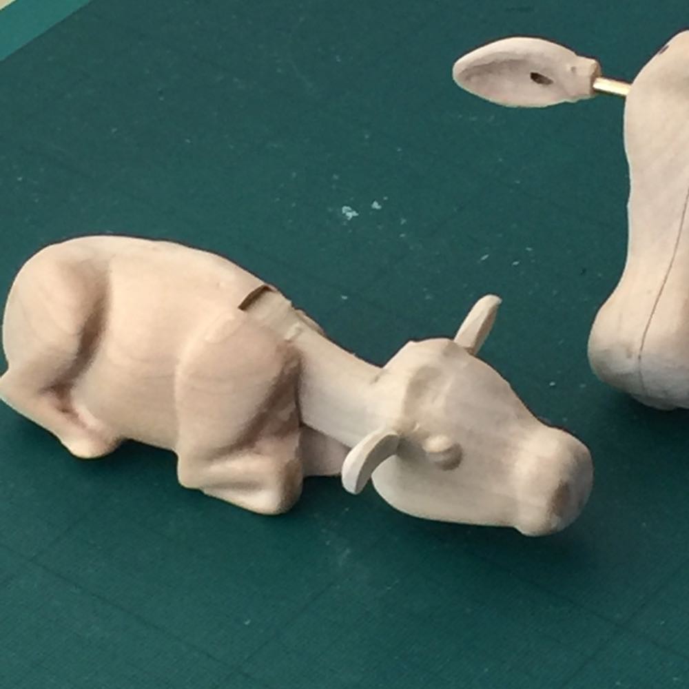
Once I have a foam prototype that I am happy with I make the part from lime wood. I make the basic shape on the router, usually in 2 halves so that cavities for the internal mechanism can be cut in. I then finish by hand. I am really pleased with this representation of a new born calf.
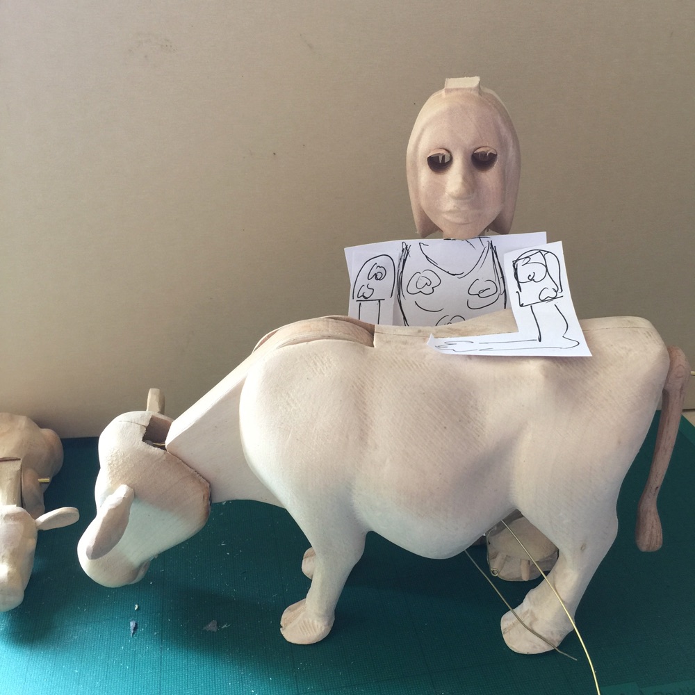
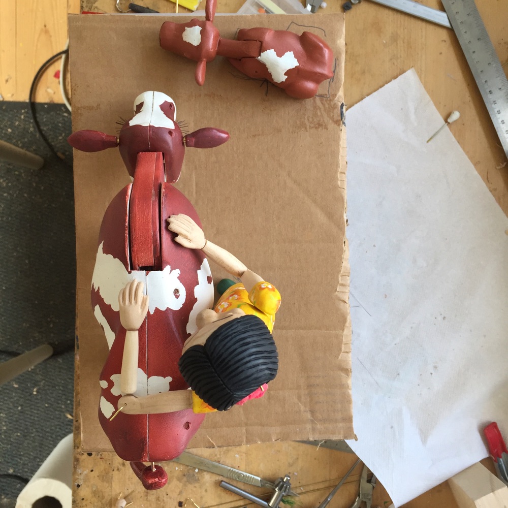
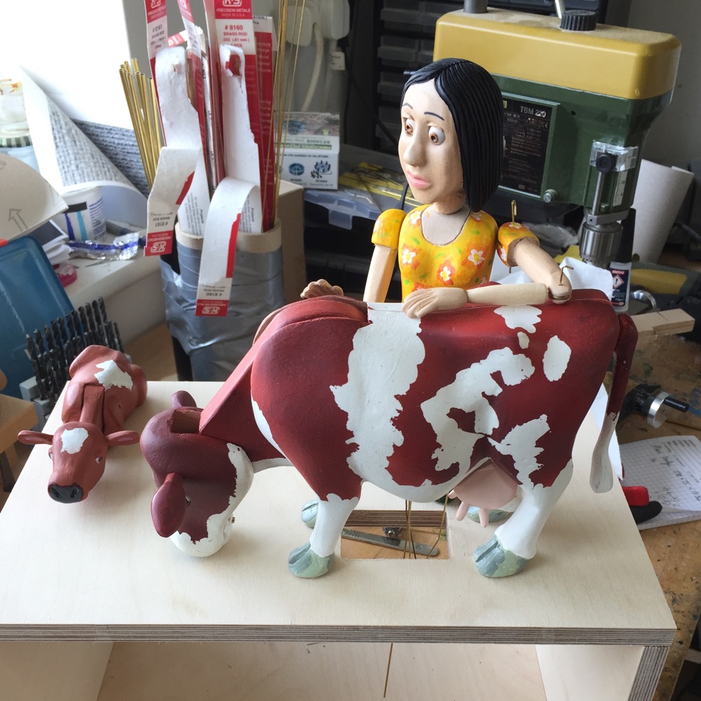
Mocking up the position and size of the lady.The dimensions are important as she needs to be the right height for scratching the cow's back. Although the scale of the pieces is not realistic the relative sizes create a good aesthetic as the eye is drawn around the piece.
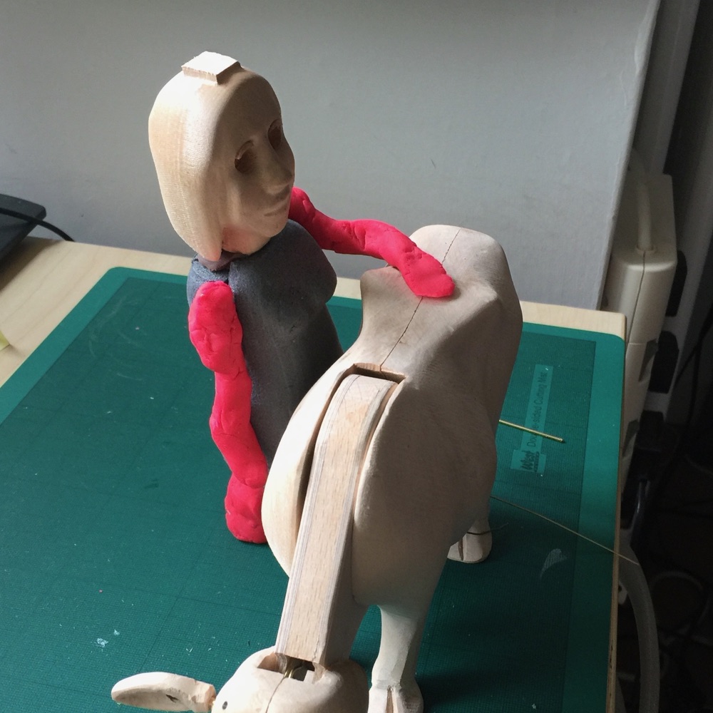
The body cut in foam. This prototype body proved to be too thick. Arms and legs are modelled roughly in Playdoh to get an idea of proportions.
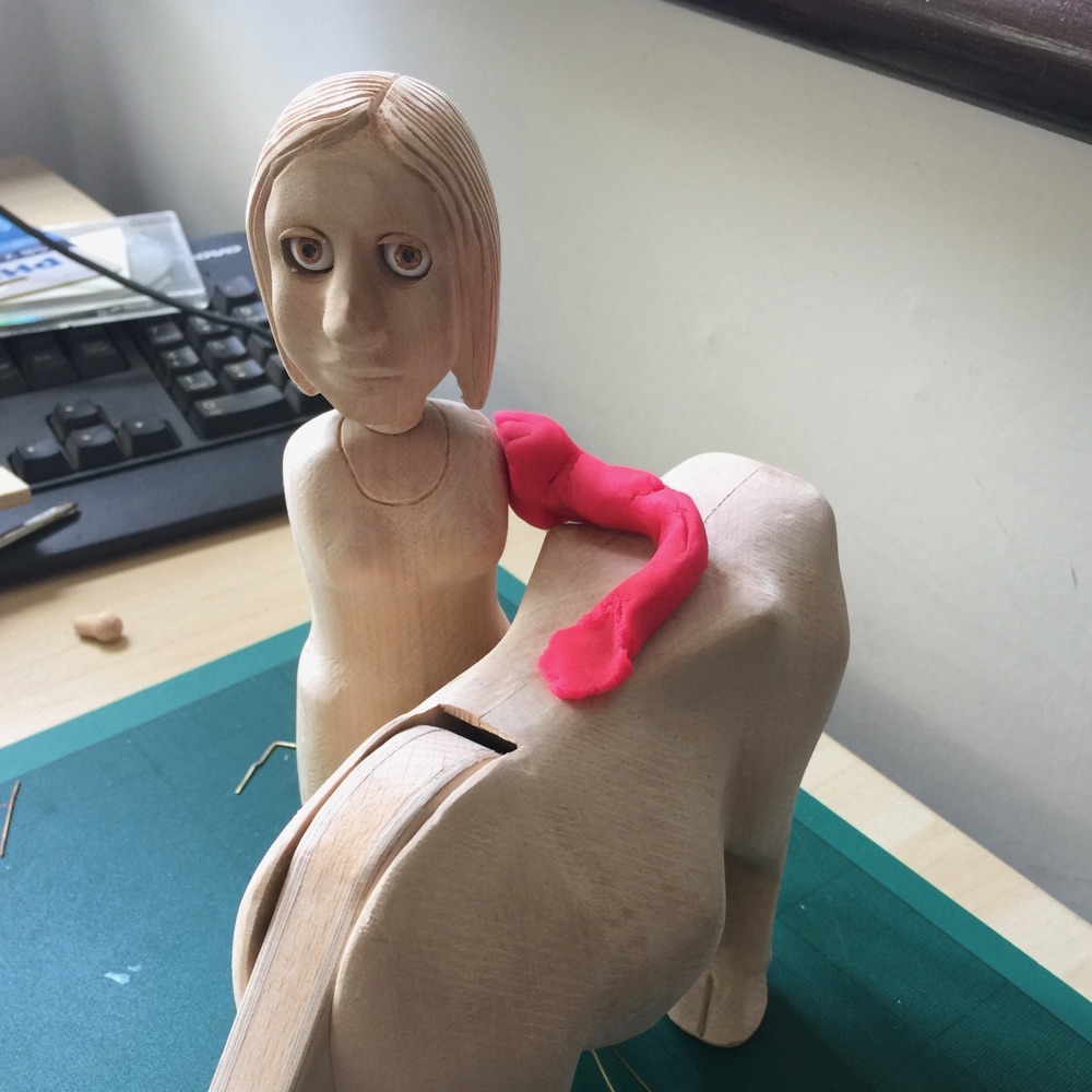
The wooden body is carved. And another model arm in Playdoh is positioned.
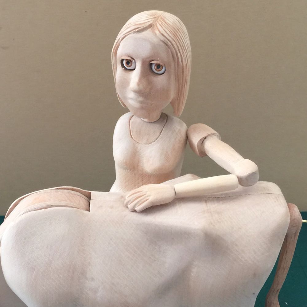
The arm carved from lime wood. This arm will scratch the cow's back. The lady's hair has been carved and eyelids have been fitted.
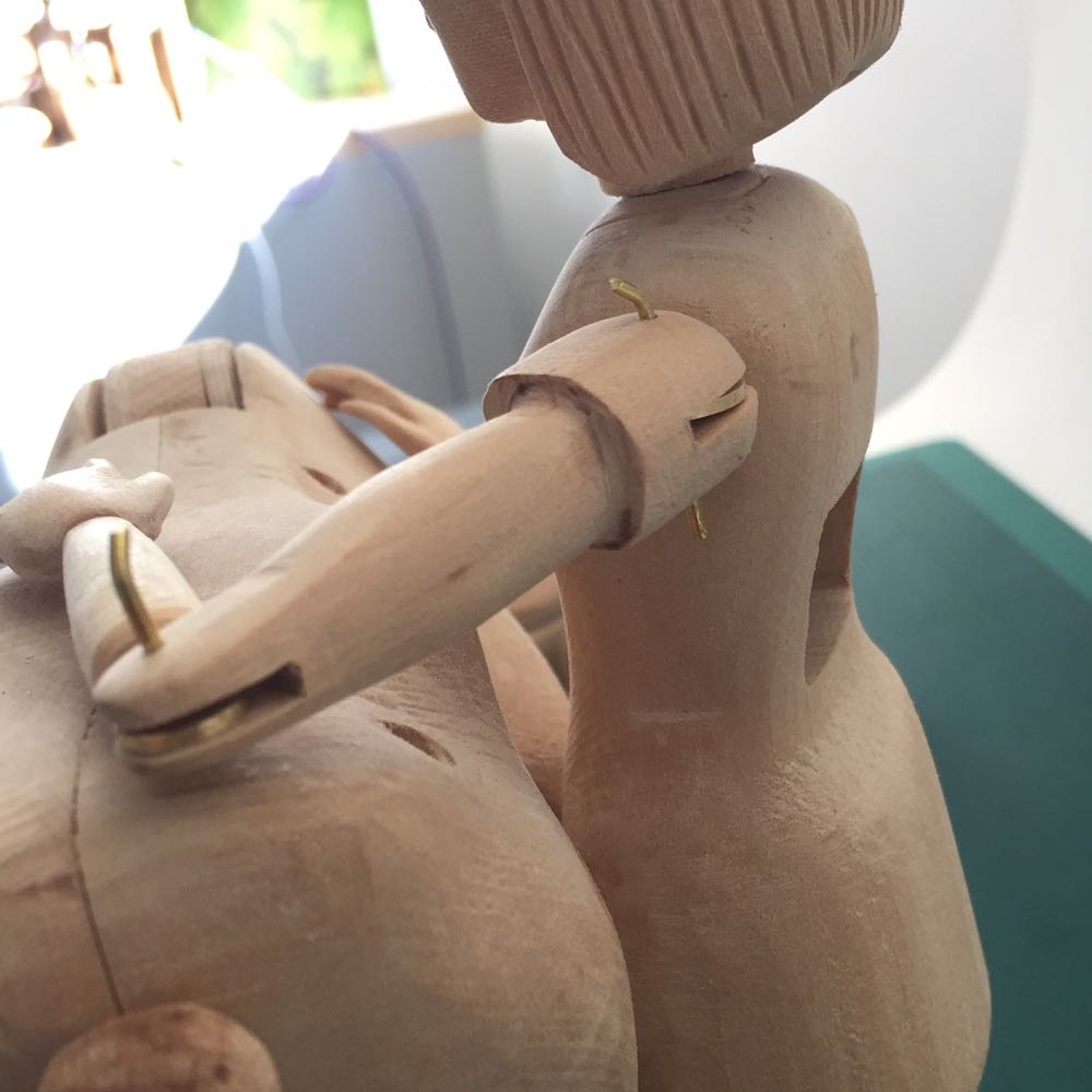
Showing the brass hinges for the arm. I used brass as this enables a thinner hinge rather than for its strength.
Gesso applied to the wood to seal the grain and create a smooth base for the first coat of acrylic paint. The gesso makes the wood's surface much harder.
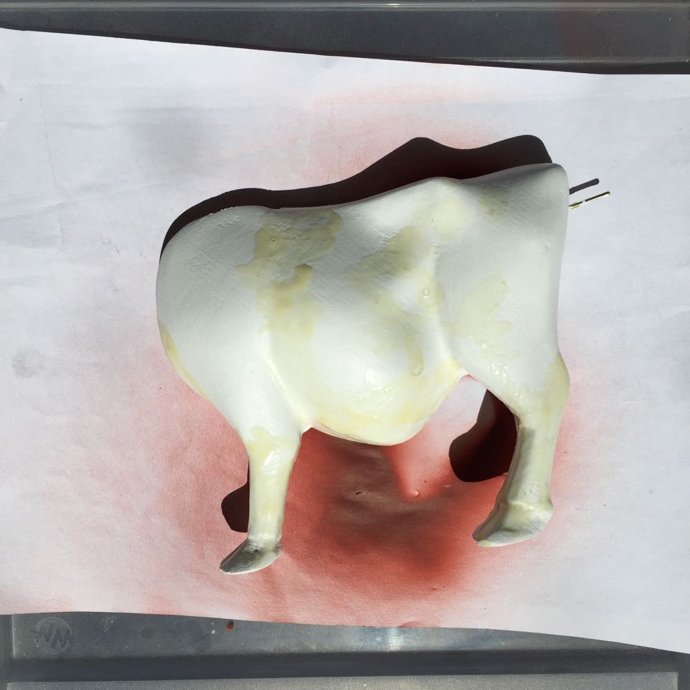
Masking fluid applied onto the acrylic base coat. Difficult to spot against the white acrylic paint.
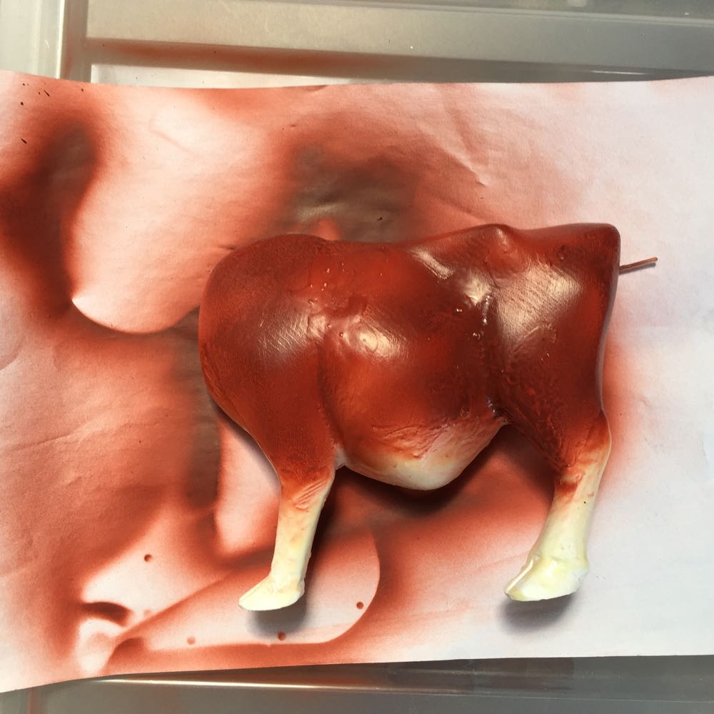
Spraying over the mask with an airbrush.
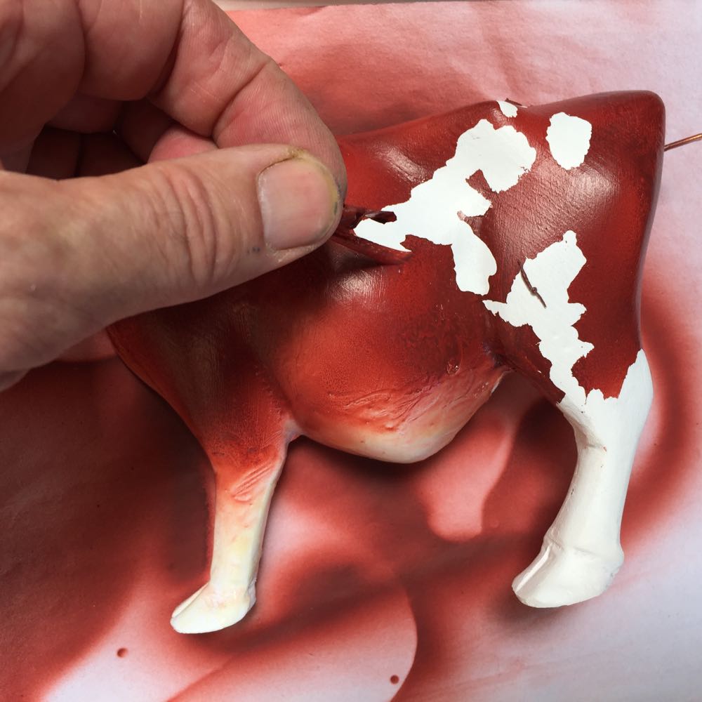
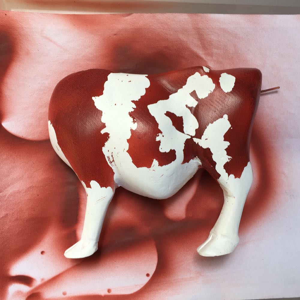
After a few minutes it is very satisfying peeling off the latex mask to reveal the pattern below. This technique gives food definition between the colours and doesn't give the different paint thicknesses that would result from hand painting. Painting brown acrylic over a white base would need several coats to give a consistent finish.
When the latex is removed there are a few areas where the spray has got through the mask. These are easily touched up with white paint.
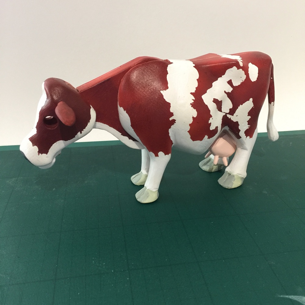
Painted but not yet varnished. I use 2 coats of acrylic gloss followed by a final coat of dead flat acrylic. This gives a finish similar to that seen on vinyl art toys.
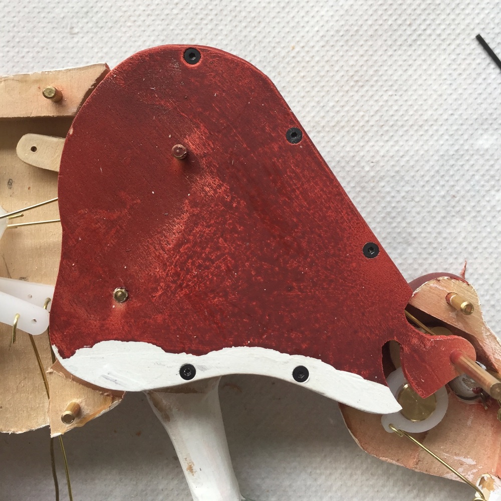
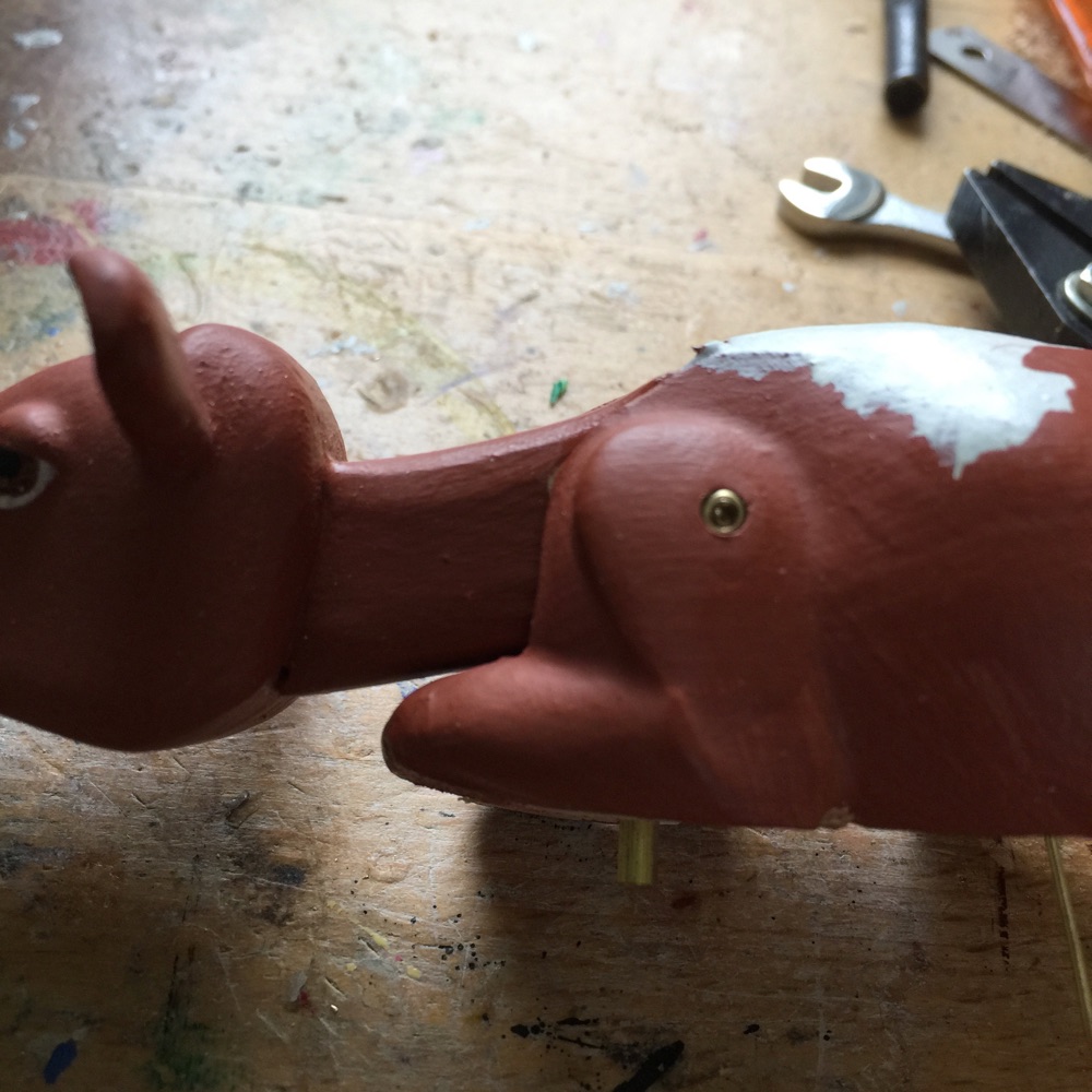
I try to make my automata so that they can be adjusted if necessary. In this case the parts of the cow are secured by hex screws into brass pins.
The cow's eyes close as it stretches forward. This is for when it licks the calf.
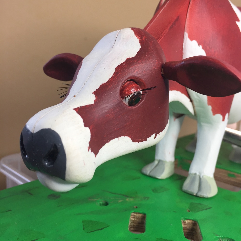
Eyelashes are made from paint brush bristles. These are inserted into micro holes, drilled with a steady hand.
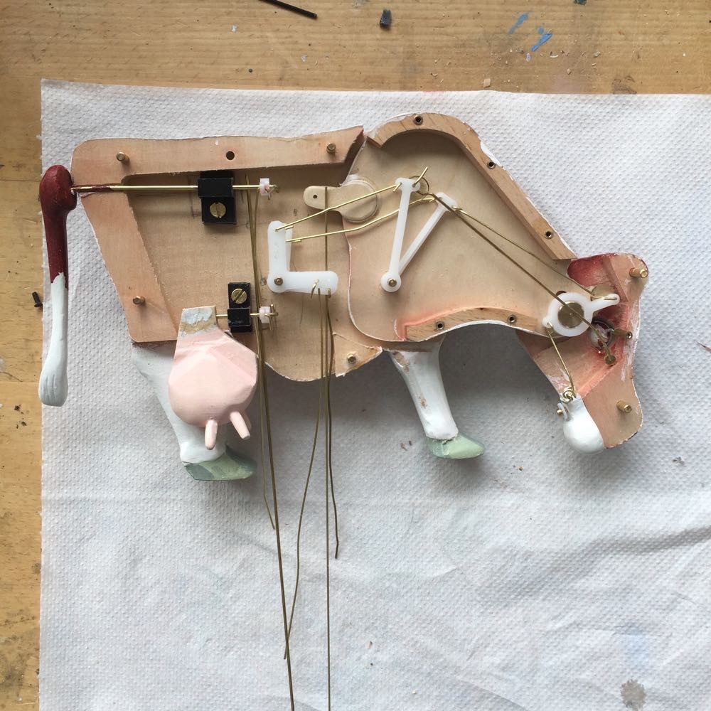
I use Delrin for linkages inside the cow. This is an engineering plastic that has good strength and is easy to work with. In this project it is necessary to get the control wires to the head but not have them affected by the neck bending. In order to achieve this the wires have to travel through the axes of the neck joints so that the distance travelled head to body remains constant whatever the position of the head.
The placement of the parts is laid out on a sheet of cardboard to get an idea of the best size.
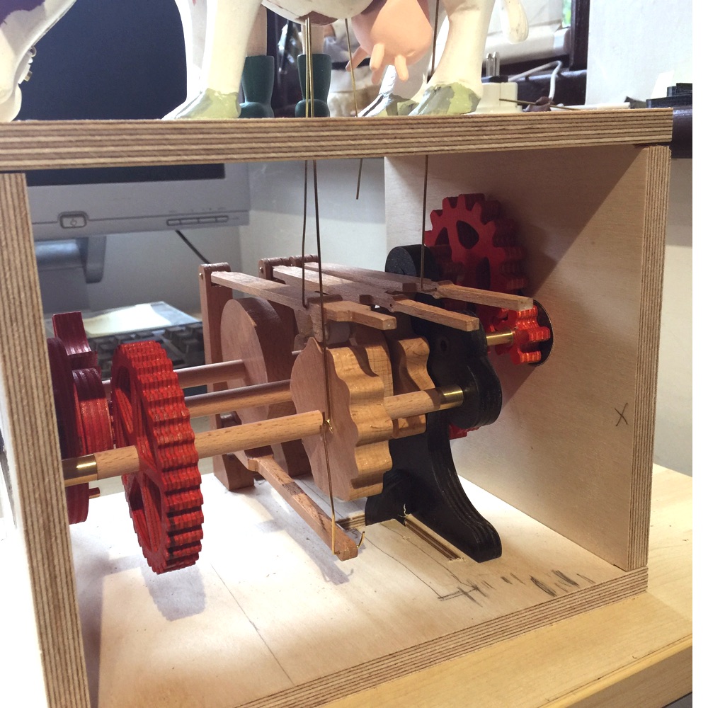
A prototype mechanism box ready for constructing the cams and gears etc.
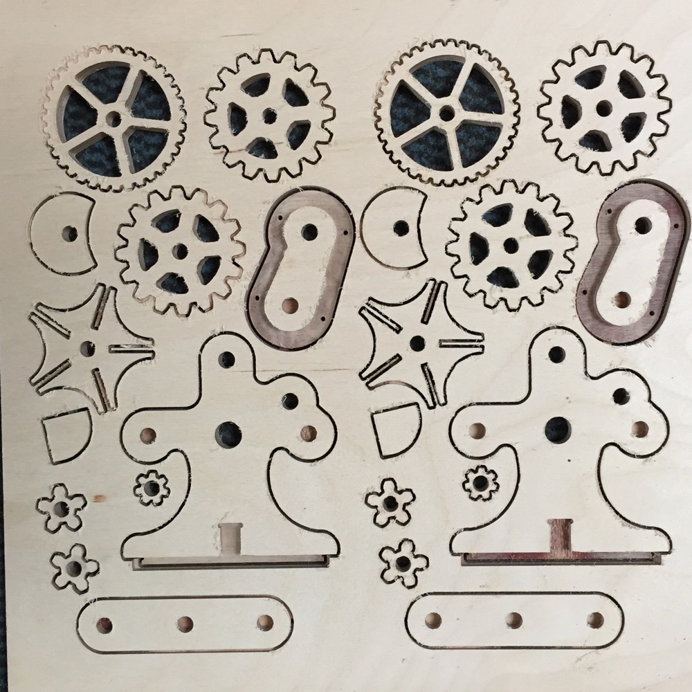
Gears cut from 12mm birch plywood. This top quality plywood is strong and stable allowing close tolerances to be achieved. This is especially important for Geneva wheels as they can jam if not precisely made.
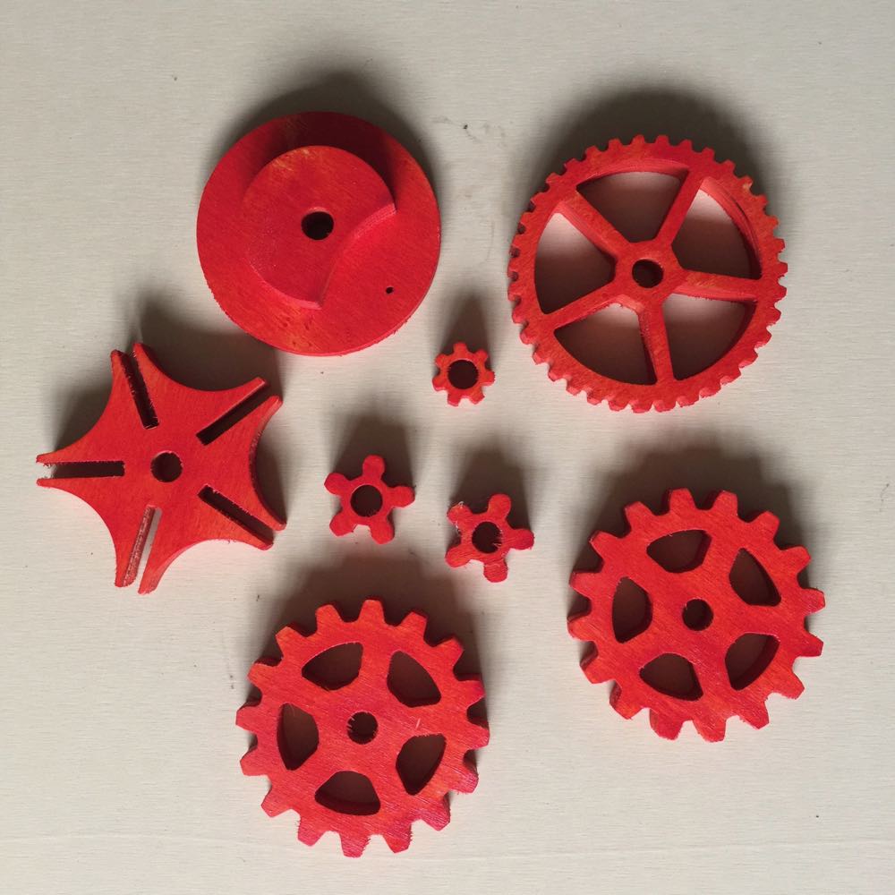
Gears spray painted with acrylic paint and then finished with several coats of wax finish acrylic lacquer.
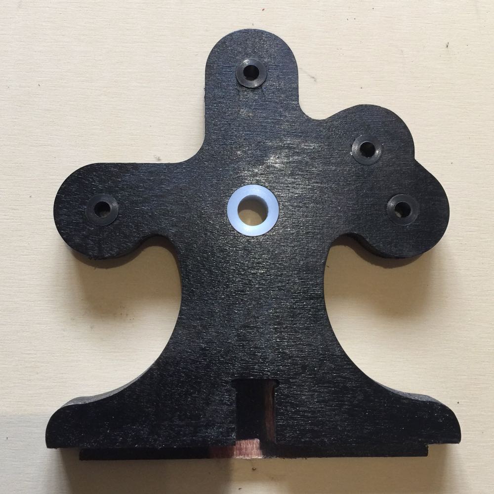
Nylon inserts are made to hold the brass axle ends. These ensure very smooth running and durability.
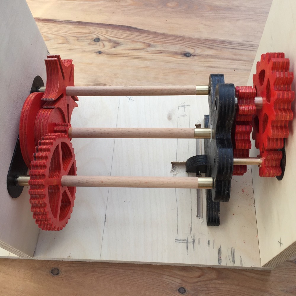
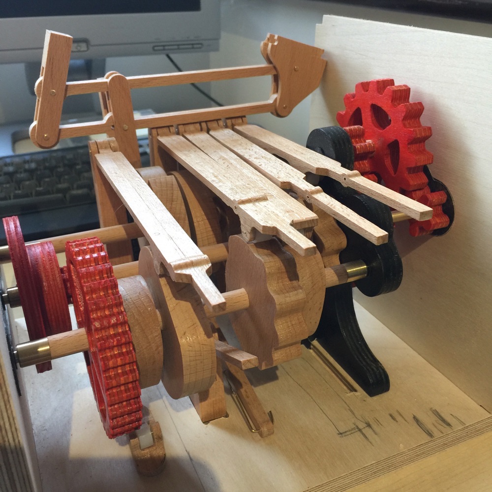
Fitting of the gears into a test frame. The space in the middle will hold the cams. The ends of the axles are made of brass for durability and smooth running.
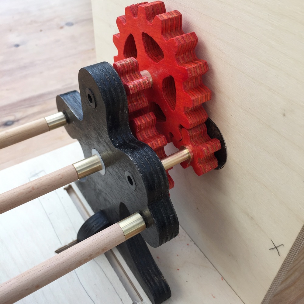
These are the speed reduction gears. Reducing the speed results in a smooth and light movement and a dissociation of the crank turning and cams moving.
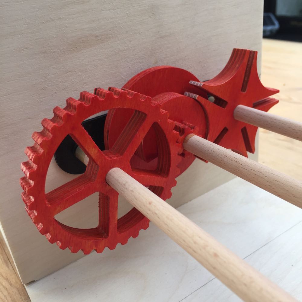
These are the timing gears. The Geneva wheel has 5 steps. The gears are 7 teeth on the small and 35 on the large giving a 5X reduction. The result is that the 2 axles are synchronised, one giving constant movement, the other giving episodic movement. I used a similar set up for A Trip to the Doctor.
A refinement of the internal mechanism and the addition of a mechanism to enable back scratching. All a tight fit.
Beginning to fit and refine the cams. Made of beech wood with several coats of acrylic lacquer. Can be a tight fit to get them all in. The cam followers and supports are made in 2 halves for strength.
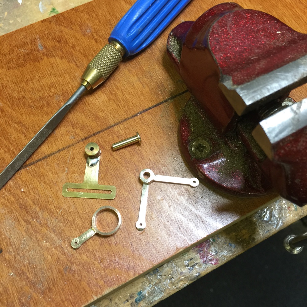
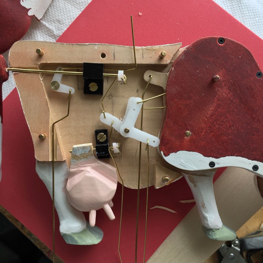
Brass linkages for the lady's head mechanism. Cut and files. Finished with wire wool.
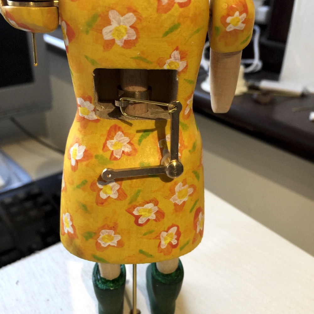
The head turning mechanism fitted. In some cases I turn the head with an axle running right through the body. Here though as the lady is standing it would be difficult to drill a hole through the centre long enough to run the control rod for the eyes. There his also little space to fit that type of cam. This arrange emts gives more flexibility.
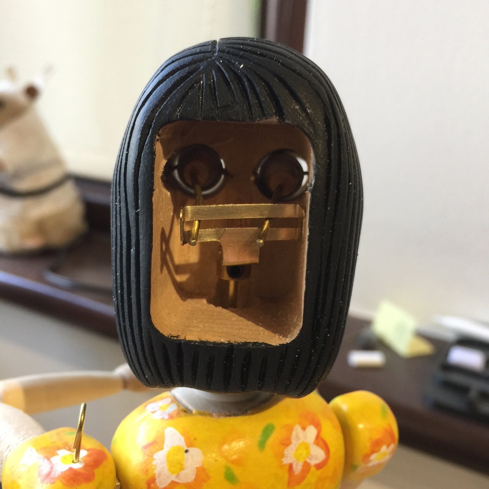
The eye fitted. The control rod attachment is attached with a small group screw to enable fine adjustment.
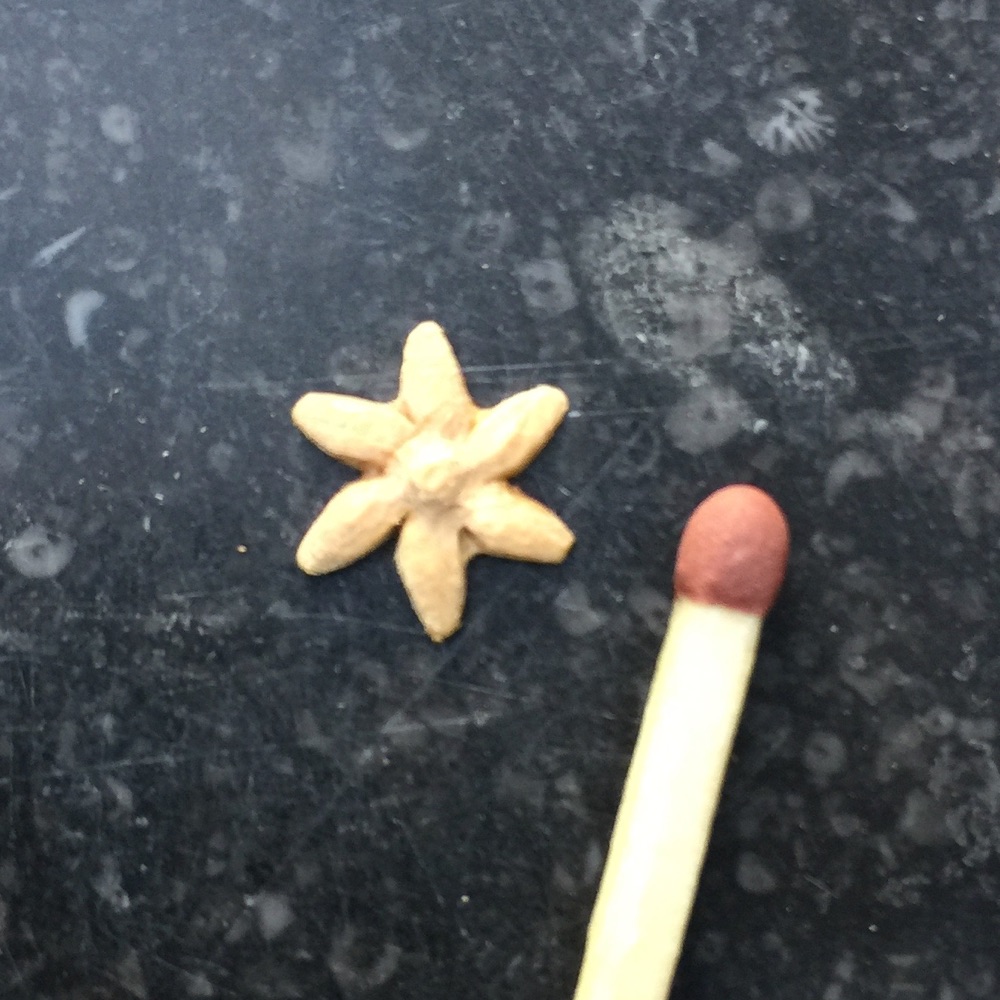
The cow's jaw is a little hidden so it in't obvious that it is chewing. The solution is a small daisy carved from boxwood that will protrude from the mouth, drawing attention to the movement.
Continuing to test fit the cams and cam followers. The mechanism to lift the heart when the cow and calf "kiss" too some thinking through as it requires a long motion that is not easy to achieve in a confined space. All seem to work as planned so now time to make the frame for the automaton.
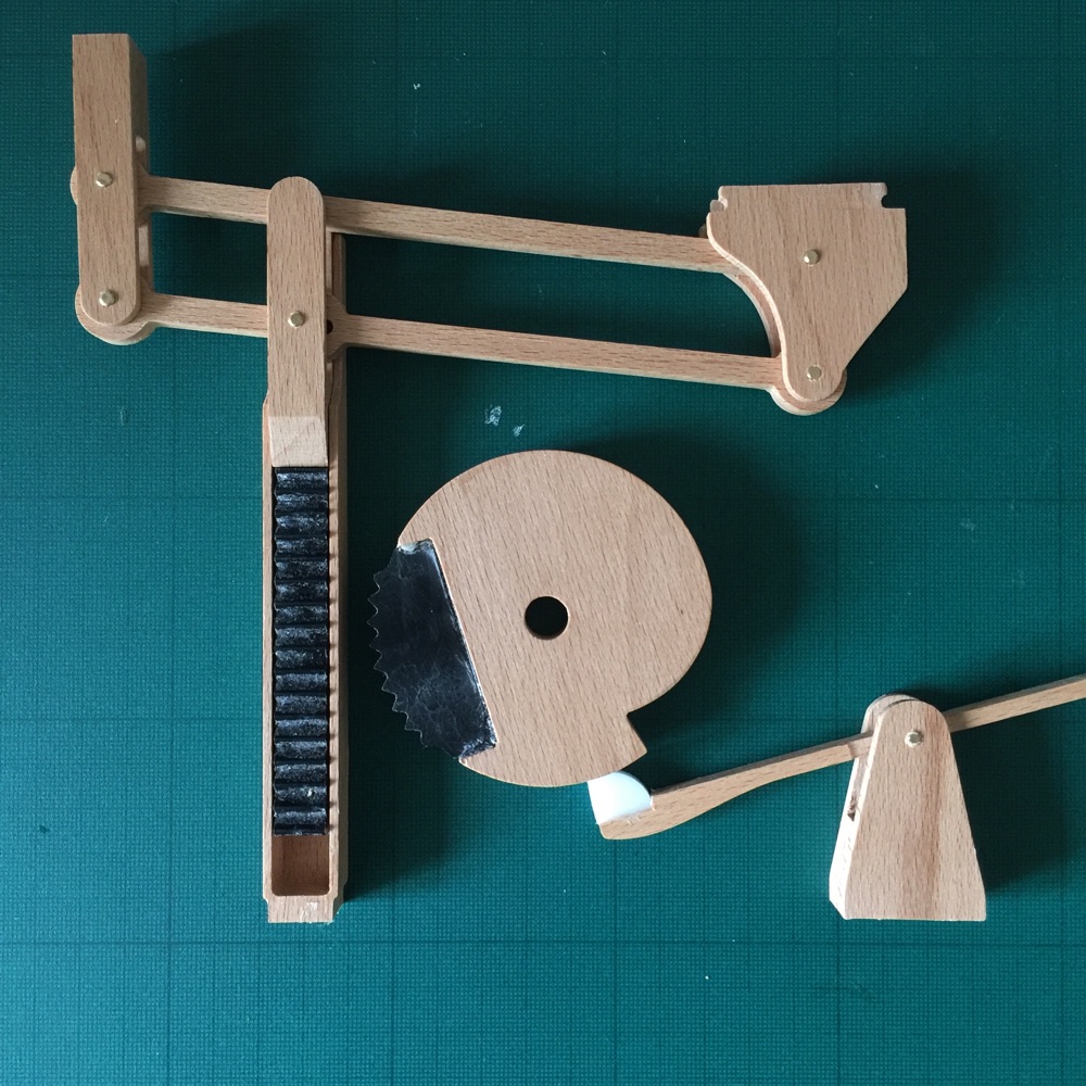
Showing the linear gear with a part toothed cam for lifting a heart. The linear gear runs in a guiding channel to prevent it moving away from the cam. The gear parts are cut from delrin, an engineering plastic, for low friction and durability. The other parts are beech wood. The lifting parts are each glued together from 2 halves to increase strength and stability. The catch in the cam is to prevent the cam from turning backwards whilst the heart is lifted as this would disrupt the smooth functioning of the Geneva wheel that drives it.The cam and catch should be at 90 degrees to the linear gear of course.
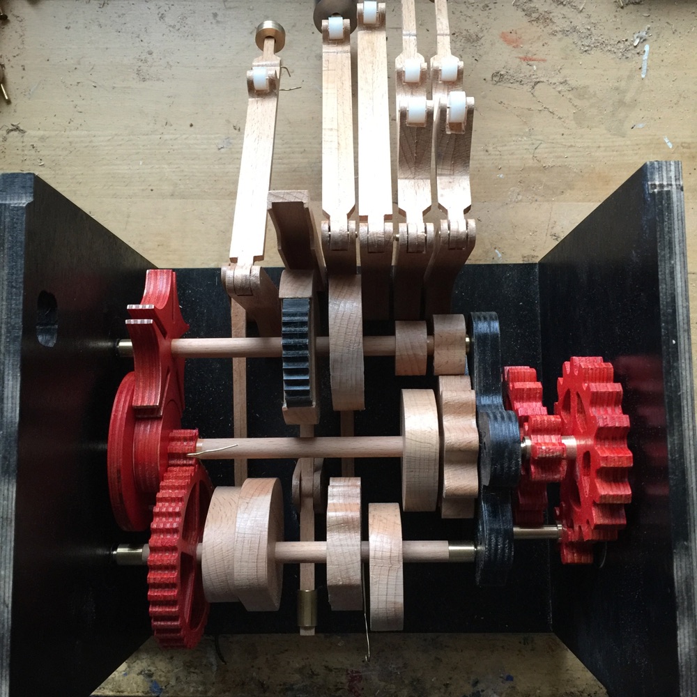
Top view of cams and gears. The nylon rollers on the cam followers can also be seen.
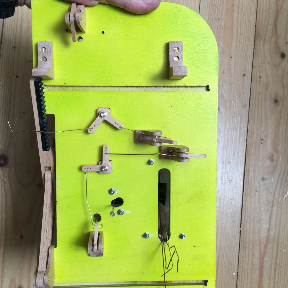
The underside of the top board. The steel nuts are holding the cow and the lady in place. I like to make my larger automata so that they can be taken apart. The sis very helpful in the build process.
Are you can see the pin that forms the neck axle. Once it is inserted it cannot be removed, except I have tapped a M2 screw thread into it so that it can be extracted if necessary by inserting a small bolt. The brass pins underneath anchor the calf to the top board.
The finished automaton plus a video can be seen here.